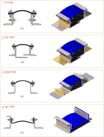
|
1.
Applications
Economizer to Air Heater Gas
Recirculation to Boiler Air Heater to Precipitator
Recovery Boiler to
Precipitator Turbo-Expander to CO Boiler CO Boiler to
Precipitator. |
|

 Temperature : 700℉~900℉ for
continuous operation, excursion to 1200℉ Temperature : 700℉~900℉ for
continuous operation, excursion to 1200℉
 Media : Low pH Flue gas from the combustion of
coal, oil or caustic black liquor.; Flue gas from regeneration process. Media : Low pH Flue gas from the combustion of
coal, oil or caustic black liquor.; Flue gas from regeneration process.
 Particulate : Transferred with
heavy fly ash from coal combustion, salt cake from black liquid fuel or catalyst
carryover from the FCCU unit at a Refinery. Particulate : Transferred with
heavy fly ash from coal combustion, salt cake from black liquid fuel or catalyst
carryover from the FCCU unit at a Refinery.
 Insulation / Lagging : Do not lag over the
expansion joint. Also, remove lagging back away from the flanges to allow
radiant cooling. Insulation / Lagging : Do not lag over the
expansion joint. Also, remove lagging back away from the flanges to allow
radiant cooling.
 Pressure
: Slightly negative for balance draft boilers, otherwise positive pressure as
much as 40-50 inches water gage. Low pressure off the Turbo-Expander. Pressure
: Slightly negative for balance draft boilers, otherwise positive pressure as
much as 40-50 inches water gage. Low pressure off the Turbo-Expander.
 Operating Conditions : Systems
usually on line for 12 to 18 months. Refineries have longer durations between
major outages. Only Power ‘peaking; plants will cycle more frequently. Operating Conditions : Systems
usually on line for 12 to 18 months. Refineries have longer durations between
major outages. Only Power ‘peaking; plants will cycle more frequently.
 Movements : Ductwork/boilers
generally have large expansions and require joint system with large lateral and
compression capabilities. Movements : Ductwork/boilers
generally have large expansions and require joint system with large lateral and
compression capabilities.
|
|
2.
Applications
Air Heater to Fossil Fried
Boiler, Air Heater to Coal Mills |
|

 Temperature : 600℉ ~750℉ for
continuous operation. Temperature : 600℉ ~750℉ for
continuous operation.
 Media : Clean ambient air pushed from the FD Fan and from the Primary Air
Fan thru the Air-heater to the Boiler both directly and thru the mills
 Particulate : Clean Air Particulate : Clean Air
 Insulation / Lagging : Do not lag
over the expansion joint. Also, remove lagging back away from the flanges to
allow radiant cooling Insulation / Lagging : Do not lag
over the expansion joint. Also, remove lagging back away from the flanges to
allow radiant cooling
 Pressure : Positive 5” water to as high 80” of water for positive
pressure boilers.
 Operation : After start up movement is normal. Severe high pressure
operating conditions may be experienced in the Primary Air Ducts of Positive
Pressure Boilers.
 Movements : Moderate high temperatures will generate moderate compressive
and movements when the unit is on line. Each change in direction in the ductwork
will generate a resultant lateral offset.
|
|
3.
Applications
Primary Air Fan to Air Heater, FD
Fan Air to Air Heater, Primary Air to Recovery Boiler,
Ambient Air to
Turbine, FD Fan Air to Recovery Boiler |
|

 Temperature : Ambient air,
-20℉~120℉ Temperature : Ambient air,
-20℉~120℉
 Media : Ambient
air Media : Ambient
air
 Particulate :
None Particulate :
None
 Heat Insulation and
Insulation : Heat insulation and insulation can be used on the outside of
the product in the case of low operating temperatures. Heat Insulation and
Insulation : Heat insulation and insulation can be used on the outside of
the product in the case of low operating temperatures.
 Pressure : Positive pressure, 40~50 inches water
gauge of higher. Turbine air inlets are slight negative pressure. Outlet at fans
may produce pressure pulsations and/or extreme turbulence. Pressure : Positive pressure, 40~50 inches water
gauge of higher. Turbine air inlets are slight negative pressure. Outlet at fans
may produce pressure pulsations and/or extreme turbulence.
 Operation : Operational conditions
have little effect on the airside ducts. Cyclical conditions and dew point have
little effect as well Operation : Operational conditions
have little effect on the airside ducts. Cyclical conditions and dew point have
little effect as well
 Movements : Joints at boilers subject to large movements. Fan outlet
joint see little movement, primarily vibration.
|
|
4.
Applications
Re-Heater to Chimney,
Precipitator to Induced Draft Fan, Induced Draft Fan to Chimney,
Induced
Draft Fan to Scrubber, Steam Generator to Stack, Precipitator to
Chimney |
|

 Temperature : Continuous operation
temperature, 350℉~500℉ Temperature : Continuous operation
temperature, 350℉~500℉
 Media : Flue gas from precipitator drawn by Induced Draft Fan; Scrubbed
Flue gas from Re-Heater going to Chimney
Turbine Exhaust Gas from Heat
Recovery Steam Generator to Chimney.
 Particulate : Minimal before scrubber systems,
negligible after scrubber systems. Particulate : Minimal before scrubber systems,
negligible after scrubber systems.
 Insulation / Lagging : Temperatures allow lagging
over the expansion joints without adverse effects. Insulation / Lagging : Temperatures allow lagging
over the expansion joints without adverse effects.
 Pressure : -15”wg after precipitators and +15”wg
after I.D fan. The ducts of scrubbers and steam generator ends are affected by
the pressure -5~+5”wg. Pressure : -15”wg after precipitators and +15”wg
after I.D fan. The ducts of scrubbers and steam generator ends are affected by
the pressure -5~+5”wg.
 Operation : Although movements are not severe temperatures will approach
dew point present potential corrosion problems.
 Movements : Moderate compressive and lateral
movements expected depending on ductwork configuration and length. Fan Joint
usually see minimal movements. Movements : Moderate compressive and lateral
movements expected depending on ductwork configuration and length. Fan Joint
usually see minimal movements.
|
|
5.
Applications
Scrubber to Re-Heater, Scrubber
Bypass to Scrubber, Scrubber Bypass to Re-Heater, Scrubber Outlet to
Re-Heater |
|

 Temperature : Continuous operation
temperature 150℉ ~350℉ Temperature : Continuous operation
temperature 150℉ ~350℉
 Media : Dry flue gas to scrubber or bypass pushed by induced Draft Fan ;
Wet flue gas at scrubber inlet: Wet, scrubbed flue gas from Scrubber (flue gas
desulfurization) going to Reheater.
 Particulate : Minimal before scrubber systems,
negligible after scrubber systems. Particulate : Minimal before scrubber systems,
negligible after scrubber systems.
 Insulation / Lagging : Temperatures allow lagging
over the expansion joint without adverse effects. Insulation / Lagging : Temperatures allow lagging
over the expansion joint without adverse effects.
 Pressure : Positive after the induced Draft Fan,
as much as 15" wg. Slightly negative, -5”wg. To slightly positive, +5”wg after
Scrubber depending on unit load and weather conditions. Pressure : Positive after the induced Draft Fan,
as much as 15" wg. Slightly negative, -5”wg. To slightly positive, +5”wg after
Scrubber depending on unit load and weather conditions.
 Operation : Although movements are not severe
temperatures will approach dew point and present potential corrosion problems.
Wet Scrubber Service is potentially highly corrosive. Operation : Although movements are not severe
temperatures will approach dew point and present potential corrosion problems.
Wet Scrubber Service is potentially highly corrosive.
 Movements : Small movements
expected. Movements : Small movements
expected.
|
|
6.
Applications
Diverter Bypass to Stack,
Diverter Exhaust to HRSG, Turbine Exhaust to Diverter Inlet, Turbine Outlet
Stack |
|

 Temperature : Continuous operation
temperature, 1000℉~1200℉, excursion to 1350℉. Temperature : Continuous operation
temperature, 1000℉~1200℉, excursion to 1350℉.
 Media : Turbine Exhaust Gas from combustion of
natural gas or fuel oil. Dry and non-corrosive. Media : Turbine Exhaust Gas from combustion of
natural gas or fuel oil. Dry and non-corrosive.
 Particulate : None. Particulate : None.
 Insulation / Lagging : Do not lag over the
expansion joint. Also remove lagging back away from the flanges to allow radiant
cooling. Insulation / Lagging : Do not lag over the
expansion joint. Also remove lagging back away from the flanges to allow radiant
cooling.
 Pressure :
Constant positive pressure generally no higher than 15 to 20 inches water
guage. Pressure :
Constant positive pressure generally no higher than 15 to 20 inches water
guage.
 Operation : Systems
with heat recovery are usually on line for 12 to 18 months. Power ‘peaking’
plants may cycle frequently as much as once per day Operation : Systems
with heat recovery are usually on line for 12 to 18 months. Power ‘peaking’
plants may cycle frequently as much as once per day
 Movements : Ductwork/ equipment expansions are
large due to the temperature. Generally, lateral movements are small due to
short, direct ductwork runs. Movements : Ductwork/ equipment expansions are
large due to the temperature. Generally, lateral movements are small due to
short, direct ductwork runs.
|
|


